plug flow reactor equation
Return A math. Reactant concentration changes in these two reactors are also compared based on their design equations to verify this.

Computational Scheme For A Plug Flow Reactor Defining The Function Download Scientific Diagram
Catalyst concentration is constant 8.

. First-order reaction wrt dissolved gas 3. Essentially no back mixing is assumed with plugs of fluid passing through the reactor. Prepare chemical reaction engineering for GATEESE 2022 Exam with these Complete lectures on chemical reaction engineering wherein Shailendra Sir has covered.
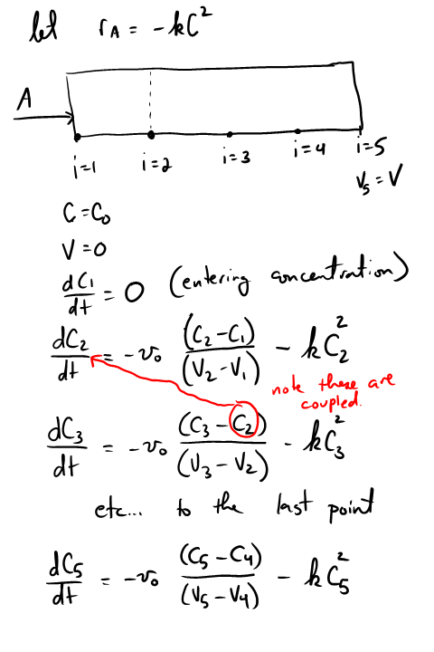
A reasonable assumption for the fluidized-bed reactor is that the fluid is partially mixed whereas the solid is fully mixed. If ax a2 in Equations 564 and 565 the primary reaction to PRODUCT is favored by a high concentration of FEED. DC dt r C Position in a PFR is equivalent to time in a batch reactor x C.
The number of moles of species i in is. Gaseous reactant is limiting 2. A reactor network is therefore necessary even if only a single reactor is considered.
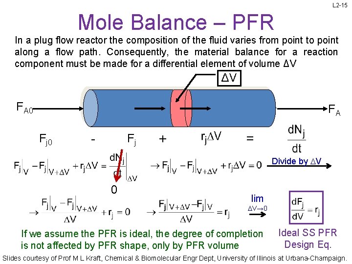
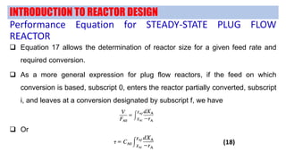
To achieve this form for plug-flow reactors we begin by applying the balance to a small differential volume in which there are no spatial variations Figure R137-1. 16 where 17 We put all the variables into a vector and the changes into a vector. The Langmuir-Hinshelwood equation you may or may not remember from CENG 390 is the form used for heterogeneous catalysis when you must worry about products or inerts using up active sites on the solid catalyst.
Examples of real reactors that. One example is in the design of chemical reactors. Gas Limiting and Plug-Flow of Liquid 1.
The reactor model consists of the continuity equations for 1 N 2 CO NO O 2 CO 2 N 2 O and NO 2 in the gas phase 2 surface species adsorbed on the noble metal surface 3a surface species adsorbed on the ceria surface 3b species in the ceria. The step wise derivation of performance equation for Plug Flow Reactor and their typical characteristics are discussedPlug Flow ReactorFlow ReactorPerfor. Plug-flow of liquid 5.
Compare ideal batch and ideal PFR mass balances. 62 which is the basic form of the design equation for a plug-flow reactor V is the reactor volume G is the total mass flow through the reactor Cao is the concentration of A at inlet in moles per unit mass of feed Xa is the fractional conversion of A and r is the reaction rate. Constant gas-phase concentration 4.
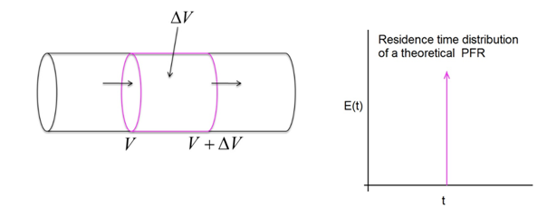
In an ideal PFR is the absolute residence time for mass flowing through the reactor not the average residence time as in a CSTR. DC d r C Ideal batch. Liquid is nonvolatile 7.
And the 4th equation in our plug flow reactor model becomes. In fact real reactors can be modeled as networks or combinations of multiple plug-flow and stirred-tank reactors Towler and Sinnott 2013. Plug flow reactor residence time distributions.
Finite gas-liquid liquid-solid and intraparticle gradients Key Assumptions. Comparing Equations R137-1 and R137-2 R137-2. A batch or plug-flow reactor maintains higher average concentrations of feed CFeed than a mixed-flow reactor in which the incoming feed is instantly diluted by the PRODUCT and BYPRODUCT.
Plug flow reactors and perfectly-mixed flow reactors are compared in the former chapter and the conclusion is that plug-flow reactors are usually advantageous over perfectly-mixed flow reactors for normal reaction kinetics. As for the fixed-bed reactor we shall first consider. Add a Plug Flow Reactor to the flowsheet and connect the Feed and Product streams remember a shortcut for toggling into and out.
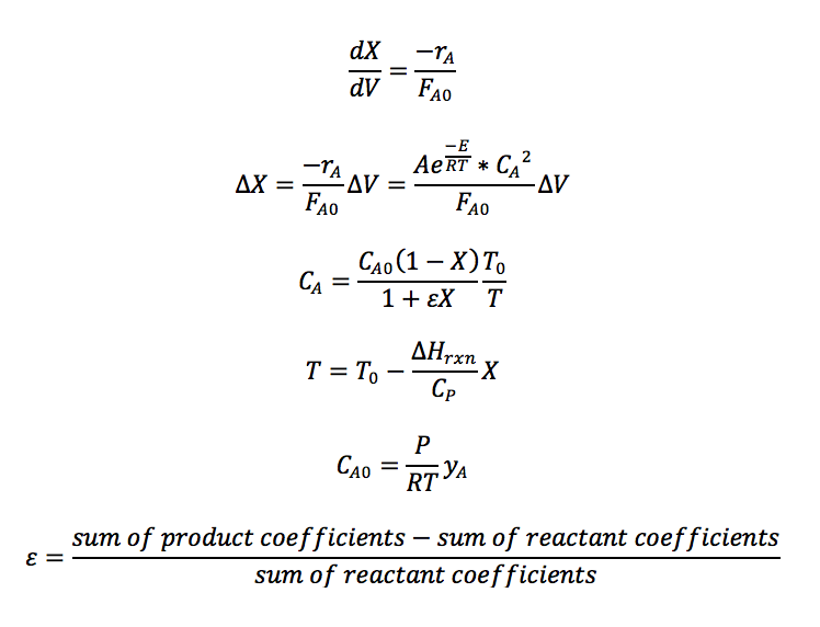
This results in differential equations that need to be integrated to find the reactor conversion and outlet temperatures. This equation can be integrated along the length of the reactor to yield relationships between reactor resident time and concentration or conversion. Exp -Ea const.
While reactors by themselves just define the above governing equations of the reactor the time integration is performed in reactor networks. Import scipyconstants as const function for the Arrhenius equation def arrh A Ea T. If we assume that the fluid is in plug flow the residence time distribution of the solids will be given by exp -t.
Plug-Flow Reactors are often used to simulate ignition delay times emission formation and catalytic processes. The plug flow model has many practical applications. The fixed-bed laboratory reactor is regarded as an ideal isothermal plug flow reactor.
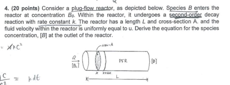
Derivation of the design equation for a plug flow reactor with second order kineticsPresented by Professor Alan Hall University of Huddersfield. The reaction occurs along the flow path. Other simplifications used are.
Solved 4 20 Points Consider A Plug Flow Reactor As Chegg Com

Introduction To Energy Balances For Plug Flow Reactors Youtube

Mole Balance On A Plug Flow Reactor Youtube
L 2 1 Review What Size Reactors To
Matlab In Chemical Engineering At Cmu

Sizing A Plug Flow Reactor Pfr Youtube
Plug Flow Reactor Pfr Sizing And Conversion Example Youtube
Plug Flow Reactor Vapourtec Ltd

Plug Flow Reactors Pfrs

Plug Flow Reactor Design Equation Youtube
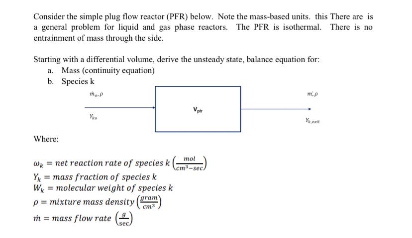
Solved Consider The Simple Plug Flow Reactor Pfr Below Chegg Com
Plug Flow Reactor Model A Plug Flow Reactor Pfr Model Is Used By Justin Mitchell Medium

Design Equation Of Plug Flow Reactor Chemical Reaction Engineering Lecture 08 Hindi And Urdu Youtube
Plug Flow Reactor

Plug Flow Reactor Overview Youtube

Cstr Vs Pfr Differences And Performance Equations Youtube

Plug Flow Reactor With First Order Kinetics Performance Equation Youtube

Isothermal Plug Flow Reactor Part 1 Youtube
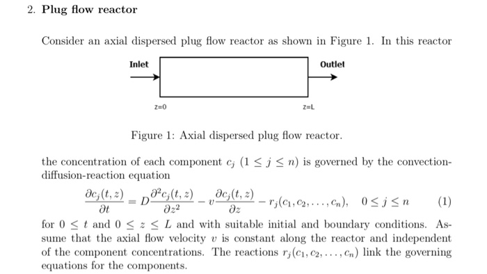
2 Plug Flow Reactor Ler An Axial Dispersed Plug Flow Chegg Com